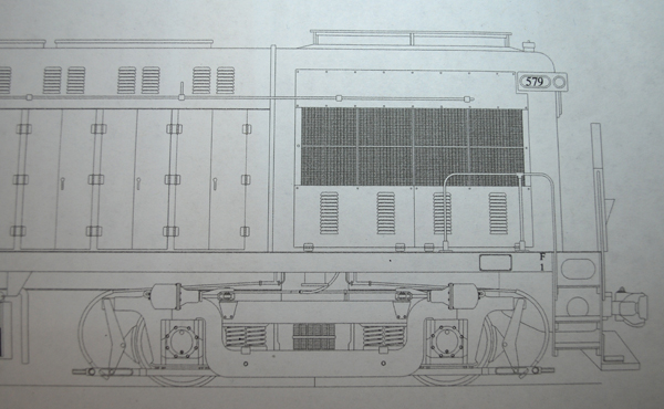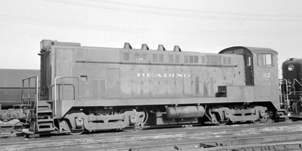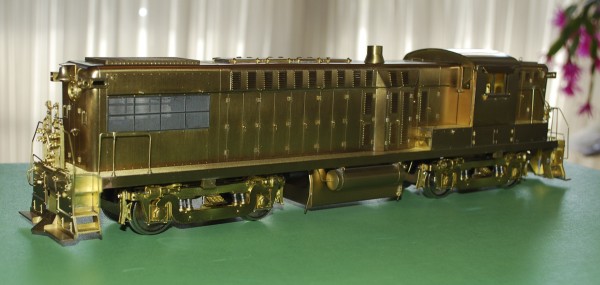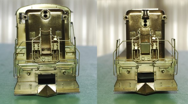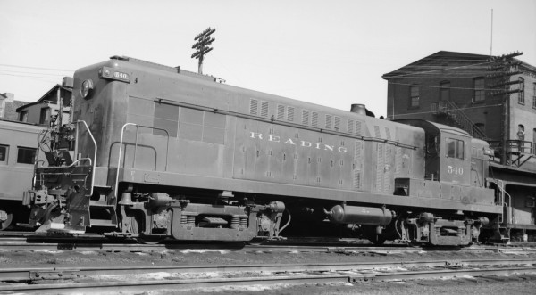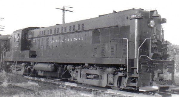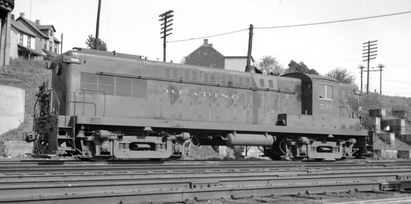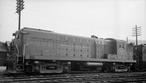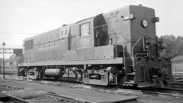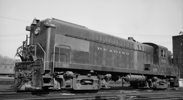
On the Reading AS-16’s there were four rows of louvers under the engineer’s side air intake on the long hood, as seen on this detail of my brother’s drawing. These are missing on my pair of Overland AS-16’s. I’m not going to punch them in the brass sheeet and the thoght of cutting them into the sheet does not appeal to me either.
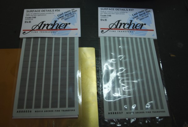
I thought this would be a good test for Archer Fine Transfers new surface details #36 O Scale 14″ Louvers and #37 O Scale 6″ Louvers. So I ordered them in last week. I have to say that they arrived a couple of days after placing the order on their website. I had ordered their rivets before but had not had a chance to use them yet.
I thought it would be a good idea to test them out before using them on the model. Even though these sheets are a little expensive there are plenty of louvers on the sheet.
They are handled just like decals but they are more fragile than decals. I soaked them in water until they released from the backing paper and then applied them to a test sheet of brass. They adheared fine, I did use Champs setting solution on them after they had dried.
For my needs for the AS-16 niether size is really correct. So I experimented with cutting the 14″ down to 8″ width. My first attempt did not work as I slide the blade down the decal. This cause the ends to chip away. I did say these details are fragile. My second attempt worked much better, I cut through the decals in a chopping motion and did not have any chipping of the detail.
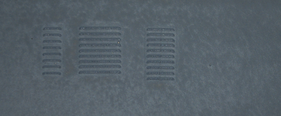
Here is the test in primer. As I mentioned the left column, the 6″ louvers are spaced too far apart and are too narrow. The middle column is the 14″ louvers. They are close to the correct spacing but are too wide. The third column is the cut down 8″ column from the 14″ details. There is a hint of overlap in this image but remember column one is 1/8 of an inch wide, so they are reproduced here at about 400% of the actual size.
I like them. I’ll try them out on the Baldwins in the next couple of days.
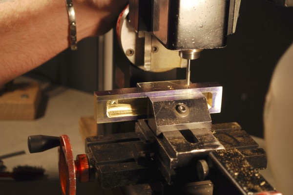
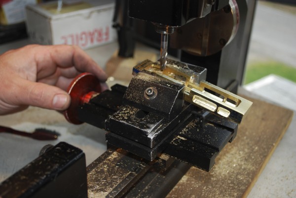
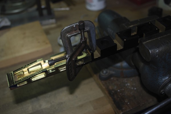
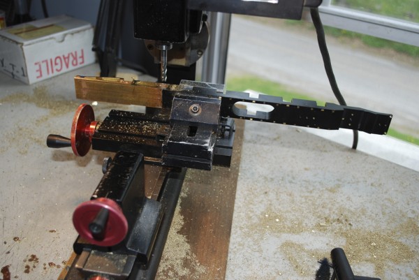
Here is a quick photo-show of last weekend’s work making of the tailbeam. The work was done under the guidence of Matt Forsyth. I can’t thank him enough for making the machine work seem easy.
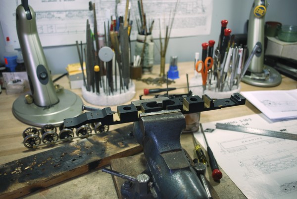
Sunset Frame in the vise, the two tail pieces have been heated and removed.
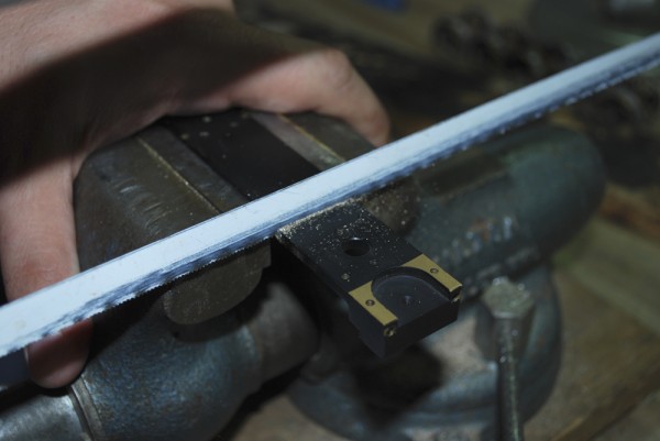
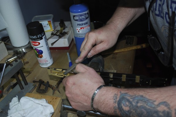
The toughest part of the operation. Putting a hack saw on the models frame.
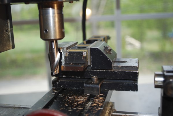
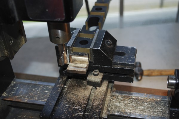
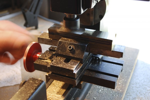
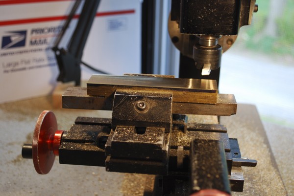
With the tail section removed the hack saw cut is trued up in the milling machine.
Milling the step in the rear of the frame.
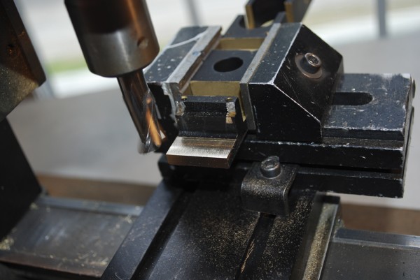
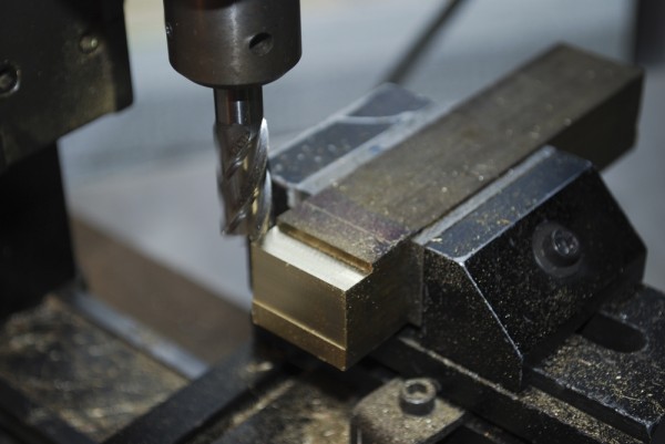
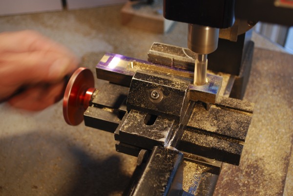
Cutting in two directions now. Milling the step and the face at the same time. You can still see some of the solder that held on the tail sections of the Sunset frame.
Continuing to cut the step back until the paint that was at the top of the step is removed.
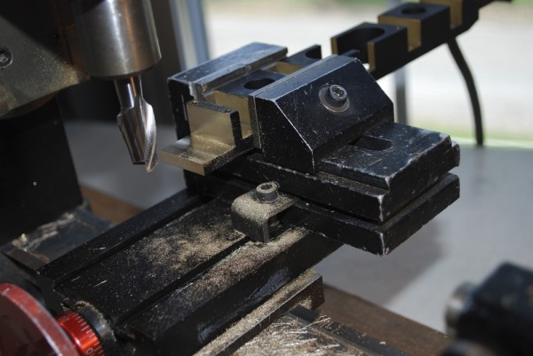
Milling the step into the block.
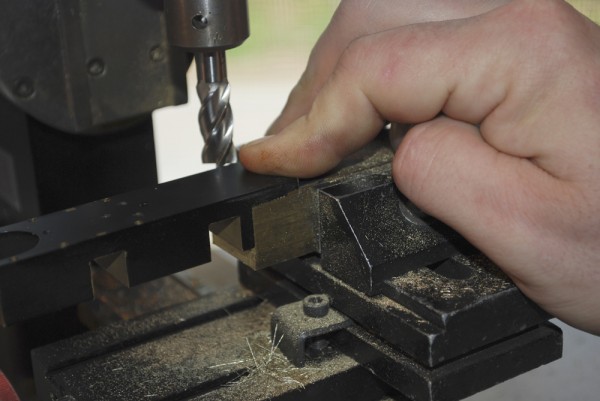
Testing the fit of the frame into the step.
Starting the fly cut to thin down the block. I will remove the material down to the scribed line.
Still flycutting the block. You can see we are getting closer to the line on the block.
Milling the center slot in the tailbeam.
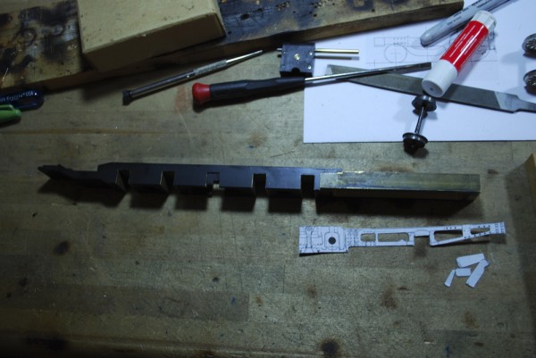
Tailbeam and frame are set together. The template for the side holes is in front. The shapes will be transfered to the tailbeam.
Back in the milling machine the corners of the holes are being plunge-cut. You can see the layout lines scribed on the side.
After all the side holes are opened up the angle cut is being done to the tailbeam.
The tailbeam and frame are clamped together and checked for alignment. Once straight, they were turned upright and soldered together.
After soldering the two together the tailbeam is machined to the finish size of the sunset frame.
Here Matt is finishing up the side of the frame with a file.
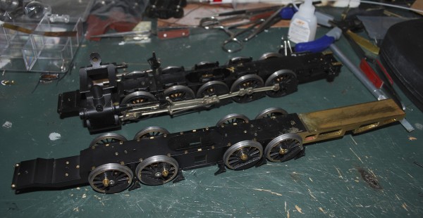
K1 Frame starts to take shape. Sunset I1sa frame in back.
Well I’ve had my first lesson on the milling functions of my Sherline lathe/milling machine. I just spent a nice weekend up above Scranton learning how to use the machine. My friend Matt Forsyth was patient enough to guide, teach and watch me timidly use the machine. I did get better as we did more.
The project was to make a new tail-beam for theframe of the RDG K1 2-10-2. Here you see a photo of the progress. The new tail-beam has been made and attached to the frame (the next Sunset PRR I1sa donor frame is pictured behind). It’s missing the main driver because that is part of the next work on the model, changing the main driver to a disc driver. More on that later.
One of the toughest things about the process was taking a hack saw to the rear of the I1sa frame to start the project.
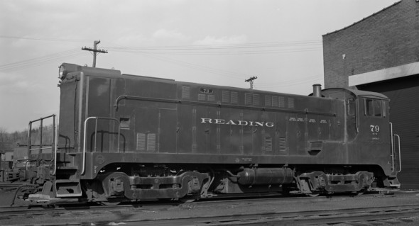
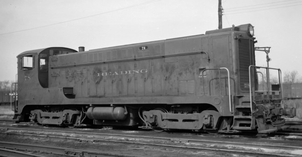
The Reading class OE-10 applies to both VO-1000 and early DS4-4-1000 end cab switchers. While the majority of the switchers on the Reading where concintrated in the Philadelphia area, the OE-10’s were seen in all parts of the railroad including the Shamokin Division.
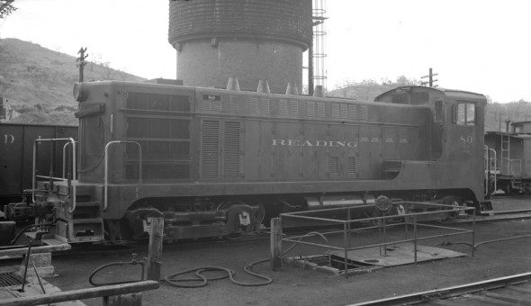
The first pair of VO-1000’s #80-81 arrived in August of 1940 and had ovel grills like they early VO-660’s.
Reading OE-10 #80 at Shamokin, PA
The next VO-1000’s to arrive looked very muck alike. They had curved walkway boards, point radaitor grills in the front and single exhaust stacks near the cab.
Reading OE-10 #78
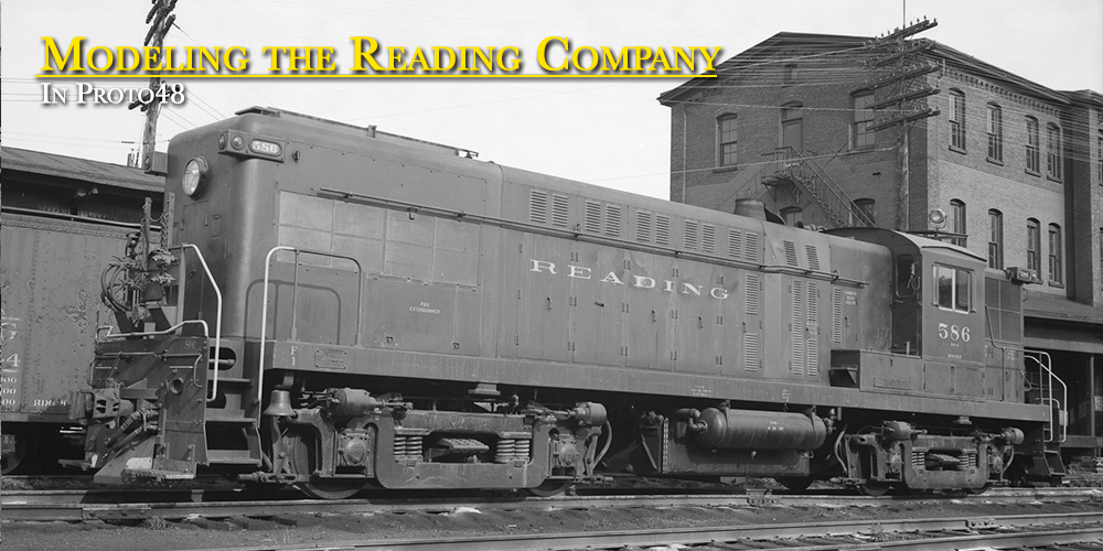
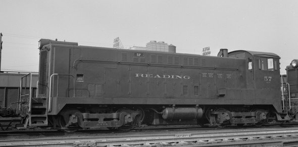
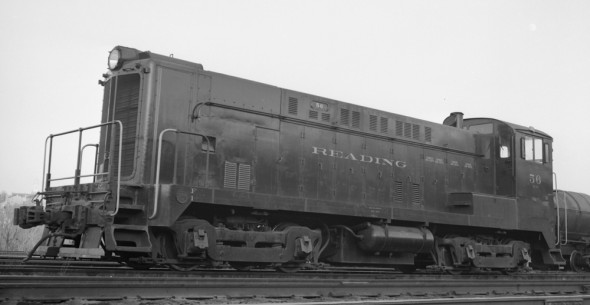
In September of 1944 the Reading received #55-59, their last of their VO-1000’s from Baldwin. They differed from the earlier VO’s by having square cornered walkways.
Reading OE-10 #57 is an example of the later car body style for the VO-1000
Reading OE-10 #56
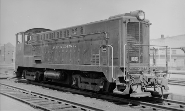
The next group to be delievered #34-36 were amoung the first group of DS4-4-1000’s to be built. According to the Baldwin book they were built with parts left over from the VO production. The #35 has a VO radiator.
Reading OE-10 DS4-4-1000 with a VO front end
The rest of the DS4-4-1000’s had flat radiators. The DS4-4-1000’s were delievered with four exhaust stacks.
During the war Baldwin had found that the exhaust back-pressure could be reduced with the four stack exhaust and it reduced the heat the generator was subjected to increasing its efficiency. Restrictions from the War Production Board prohibited making the change during the war to the VO-1000’s. After the war Baldwin recommended that the change be made to the VO-1000’s Reading did that to some of their locomotives during later overhauls.
References:
Diesel Era – 1996 March/April – Reading’s Repowered Switchers.
Diesel Era – 1998 March/April – Reading’s First-Generation Diesels by by Paul K. Withers
Reading Diesels Volume 1 The First Generation – by Dale Woodland Photograph’s from George Losse Collection scaned from negatives.
As more of the PRR models finding continue to find new homes. A second AS-16 arrived yesterday in as nice a condition as the first one. I can’t wait to get these painted.
Last night’s trading also brought a SGL G-3 to the roster. This will move my modeling clock back into 1952.
Yesterday at the Strasburg 2-Rail O Scale Train Show the first of my Sunset I1sa’s went to a new home and a new baby came home with me, an Overland Baldwin AS-16.
Possible prototypes that could be built from this model:
1951 built AS-16 Freight Unit: Add rain gutter on cab roof Remove the fuel tank between the trucks
1951 built AS-16 Passenger Unit: Add rain gutter on cab roof
1952 built AS-16 Freight Unit: Add rain gutter on cab roof Add Dynamic Brake opening on the short hood. Remove the tank behind the cab on the short hood
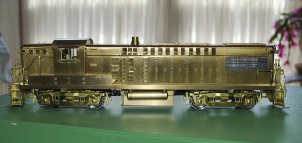
The Reading Company had been a long time buyer from Baldwin locomotive Works. They had bought steam locomotive from them and had been very happy with the diesel switchers made by Baldwin. When the railroad turn to the road switcher models they again turned to Baldwin and bought their AS-16 model.
There are good sources of information on these units in print. Here is a short list:
Diesels of the Reading Company Volume 1, Paul K. Withers
Reading Diesels Volume 1 The First Generation, Dale Woodland
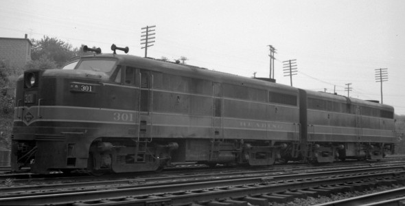
While each group of AS-16’s were different they did have a few things in common. They all had walkways over the top of the vent in the roofs. Most had louvers on the engineer’s side of the long hood under the air intakes. They all had railroad applied rain gutters applied to the cab roofs.
All the AS-16’s were delivered in the Pullman Green paint scheme, and they wore it until they were retired. As delivered they had green handrails and low numbers on the ends of the locomotives. During sometime around 1953 the handrails were painted the safety yellow. Sometime near 1956 the end numbers started to move up on the end. I would imagine so that the tower operators could see the numbers.
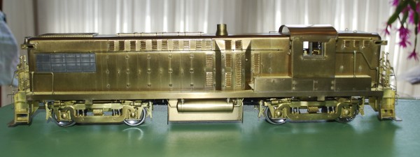
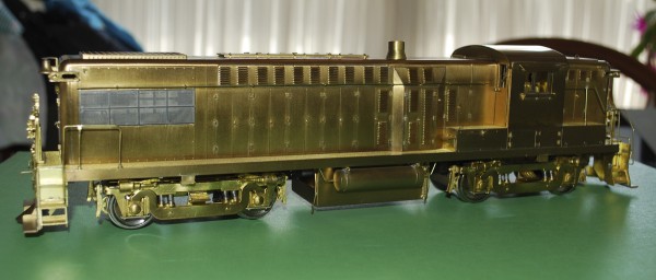
The first group #530-537 arrived on the property from 7/51-9/51. They were straight freight locomotives without dynamic brakes. They had 900 gallon fuel tanks above the frame directly behind the cabs, leaving the space between the trucks under the locomotive open. Their bell’s were mounted at the top of the long hoods. The long hoods were forward.
The next four locomotives to arrive were 560-563 were dual controlled, steam generator equipped passenger locomotives. They were based out of Green Street engine house. Their 1000 gallon fuel tank was under the frame between the trucks. The 900 gallon tank behind the cab was used for water for the steam generator. The bell was still mounted on the end of the locomotive.
The next group of freight units #538-550 arrived 10/51-11/51. Externally they differed from the first group of freight units only in the moving of the bell from the end to under the frame on the fireman’s side of the front of the locomotive. Not visible to the modeler they were heavier than the first group by 1100 lbs.
The next group of AS-16’s #576-589 arrived on the property between 6/52-7/52. They were equipped with dynamic brakes in the short hood, the bell mounted under the frame, had a 1000 gallon fuel tank under the frame between the trucks and did not have a tank of the short hood end of the locomotive. In addition they were 1300 lbs. heavier than the last group of freight locomotives.
The grill work in the short hood for the dynamic brake required the number boards be moved up the car side to the top of the short hood.
The last group of Baldwins #551-554 arrived 10/53. The order started out a 10 units but the railroad cut the order to just four units. The six locomotives left over at Baldwin were later sold to the PRSL without the Dynamic brake equipment. This was also the first use of Baldwin’s new carbody design which had enough room to move the dynamic brake equipment into the long hood. This order went back to the use of the 900 gallon fuel tank behind the cab. leaving the space under the long hood between the trucks open.
One of the problems the railroad had with the Baldwins was that they could not MU with other locomotives. Worse than that, they could not even MU with each different order. The 1951 locomotives could not MU with the 1952 units until the railroad made modifications to the load regulators, costing the railroad $16,820 per unit for the modifications. This could also account for why early photos of the Baldwins show them MU’ing with other units from the same orders. The 1953 locomotives never were able to MU with the rest of the Baldwin fleet. They had electric throttles which aloud them to MU with other manufactures locomotives but not the other Baldwins.
Most of the photos that have been published have been of the units later in life. This is understandable as they replaced steam locomotives as they arrived and most railfans tried to capture what was going away instead of what was replacing it. Why not, the new units would be around for another 15 years? What few photos are around of the units in their first years show that changes came to them early. I’ve already pointed out the numbers on the ends move higher. The hand rails get painted with safety colors and also they added louvers under the long hood’s air intake on the engineer’s side of the locomotive. This appears to have happened in late 1952 or early 1953, after my modeling period of the Summer of 1952.
Below is a chart of the Baldwin AS-16 roster on the Reading. Some of the data is pulled from the Diesel Era article on the Reading AS-16’s and some from photos. Assignment refers to engine house assignments painted on the locomotive as seen is photos of the units.
No.
Built
DB
Bell
Fuel Tank
Assignment
530
7-51
–
Top
Walkway
StC
531
8-51
–
Top
Walkway
SH
532
8-51
–
Top
Walkway
G
533
8-51
–
Top
Walkway
CATA
534
9-51
–
Top
Walkway
G
535
9-51
–
Top
Walkway
536
9-51
–
Top
Walkway
SH
537
9-51
–
Top
Walkway
G
538
10-51
–
UF
Walkway
G
539
10-51
–
UF
Walkway
540
11-51
–
UF
Walkway
R
541
11-51
–
UF
Walkway
542
11-51
–
UF
Walkway
StC
543
11-51
–
UF
Walkway
G
544
11-51
–
UF
Walkway
SH
545
11-51
–
UF
Walkway
546
11-51
–
UF
Walkway
StC
547
11-51
–
UF
Walkway
548
11-51
–
UF
Walkway
549
11-51
–
UF
Walkway
550
11-51
–
UF
Walkway
StC
551
10-53
LH
UF
Walkway
552
10-53
LH
UF
Walkway
553
10-53
LH
UF
Walkway
554
10-53
LH
UF
Walkway
560
9-51
–
Top
UF
GS
561
9-51
–
Top
UF
GS
562
9-51
–
Top
UF
GS
563
9-51
–
Top
UF
GS
576
6-52
SH
UF
UF
577
6-52
SH
UF
UF
578
6-52
SH
UF
UF
579
6-52
SH
UF
UF
StC
580
6-52
SH
UF
UF
581
6-52
SH
UF
UF
StC
582
7-52
SH
UF
UF
583
7-52
SH
UF
UF
StC
584
7-52
SH
UF
UF
585
7-52
SH
UF
UF
StC
586
7-52
SH
UF
UF
StC
587
7-52
SH
UF
UF
StC
588
7-52
SH
UF
UF
589
7-52
SH
UF
UF
StC
References:
Diesels of the Reading Company Volume 1, Paul K. Withers
Diesel Era – 1991 September/October – Reading Baldwin AS-16 Road Switchers by Gerard E. Bernet.
Diesel Era – 1998 March/April – Reading’s First-Generation Diesels by by Paul K. Withers
Reading Diesels Volume 1 The First Generation – by Dale Woodland
Photograph’s from George Losse Collection either scanned from negatives or prints.
The first of my O scale PRR models sold today and it’s not an April Fool’s day joke.
I have always thought of myself as a PRR modeler. I’ve been building and collecting O scale models of PRR equipment for over twenty-five years. About five years ago I began to focus my model building on a particular branch and a fixed period in time, The PRR Elmira Branch in 1956. This caused a refinement/thinning of the collection. Models that did not fit the time frame or location were sold off and appropriate models were bought.
I did well at the last National selling/trading off surplus models and aquiring models for the Elmira Branch. Since the National I have on a number of occasions talked about one Reading Caboose that I thought about buying but didn’t. I didn’t talk about the two Steam Locomotives that joined the roster, I talked about the one caboose that wasn’t even needed for the proposed railroad.
I have struggled with a layout design for the last two years. I have been trying to find a way to fit in more Reading models into the layout. Thinking maybe the interchange at Williamsport might be enough. It wasn’t enough.
So, I started to look at the PRR Shamokin Branch. Plenty of I1sa running, lots of hopper cars moving, so it looked like a good fit. But as I explored the branch more and learned more about it. I started to shift my focus/research from PRR as main modeling interest to the Reading as the main modeling interest.
Actually, I’ve had more fun researching the Reading these last three months since shifting to the Shamokin area then the last 15 years worth of modeling the PRR. So now I have to think of myself as a Reading Modeler.
The story of the Reading K1 2-10-2 is told very well in a 16 page article in the May/June 1981 issue of Mainline Modeler by Bert Pennypacker “Reading 2-10-2 It should have been a Texas” I do not plan to go into all the details the article did, instead I’ll go over the highlights. There is an HO scale drawing of the K1sd in the center spread of the magazine.
The Reading 3000-series K1 started as a rebuilding program in 1927 with parts supplied by Baldwin. The first 11 locomotives were rebuilt in the Reading Shops from N1’s 2-8-8-2 which were built between 1917-1919. An additional ten locomotives (3011-3020) were built by Baldwin. The 3000-3009 were classed K1-sa, 3010 was classed K1-sc, and the 3011-3020 were classed K1-sb.
The 3010 was classed K1-sc because it was built with Caprotti valve gear. This proved to be troublesome to operate and costly to maintain. In 1942 it was replaced with the same Walscheart valve gear the others locomotives had and the 3010 was re-classed as K1-sa.
In 1945 while the Reading shops were busy building the T1 4-8-4’s the K1received some modernization changes including dynamically cross-balanced Baldwin disc main driving wheels, tapered main rods and high speed drifting valves. These changes where made to increase the K1’s potential speed from 50 to 60 m.p.h. making them similar to the new T-1’s. The locomotives were re-classed from K1-sa/b to K1-sd/e.
By 1948, the diesels arriving on the railroad started to bump the K1’s from their normal routes. They started to be reassigned into the coal regions and on the Shamokin Division.
The class survived intact until the first end of steam on the Reading in the beginning of 1954. The rebuilt K1’s were first to be retired in May of 1954. Followed by the Baldwin built locomotives in March of 1955. There were No survivors from the scrappers torch.
The long hood has been fully cut off and fitted. The sand fills were cut from an extra cab and then thinned down. I hate doing that, it not hard, I just hate sanding tiny parts. The Atlas couplers were thrown in the TRASH where they belong, and Kadees have been installed.
I still have to attach the handrails, cut the front window arch in the cab windows, add a frame shim and attach the cab/hood/rear step to the frame.
Maybe I’ll get a chance to work on it this weekend. It’s not looking like it. Besides I was thinking about starting to work on the K-1 by turning the twin sand domes.