I’ve been having a conversation with Matt Forsyth for the last month or so about wheel standards. We both were involved with Proto48 when we first started in O scale, so the NMRA standard of 1.172 for wheel width is not something either of us like.
One of my early lesson on using my lathe was to turn down the width of some Gem PRR B6sa drivers. The drivers started out at 0.175 close to the NMRA specification, we turned them down to 0.145 which greatly improved their appearance.
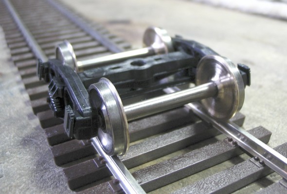
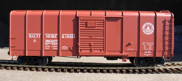
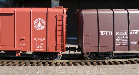
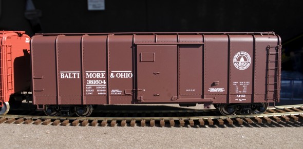
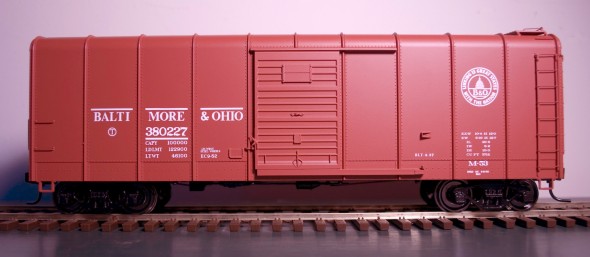
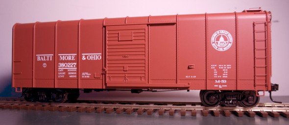
Matt has chosen to set his standards at a wheel width of 0.135″ which really makes for a fine looking wheel. He keeps sending photos like this one of an Intermountain truck with the .135 wheels under them. I had to give it a try.
Matt was working with the Intermountain Replacement wheelset that is quickly becoming the standard wheelset for a lot of modelers. First off that wheelset is way too wide at 0.162″ so it’s a natural to be thinned. Matt has been taking off the material from the backside of the wheelset. So I set up the lathe and started. The wheelsets turn very easily and were thinned to their new widths. I experimented with 0.145″, 0.140 and 0.135 taking all the material off the back of the wheel just as Matt had instructed.
They looked great! I set them up in a spare Intermountain truck and had a good look at them. Again, I say they look great! A big improvement over the stock Intermountain wheelset.
So I began to test the trucks with the new wheelsets on some of the turnouts I’ve built on the Fasttracks jigs. They rolled right through with no trouble. But as I looked closer I noticed that there was a lot of room between the guardrails and the running rails on the wheels. On the 0.135′ wheels if the one wheel was against the guardrail then the opposite wheel could hit the opposite side of the frog point. I should point out this didn’t happen on my test but it could have if the car was forcing the truck in that direction.
The first thought was simple enough tighten up the flange-way standards at the same time as the wheel standards. But My brother is also an O scaler and my layout will most likely be the only option from him to ever operate any of his O scale models. So do I really want to change the flange-way standards?
Emails were flying back and forth between Matt and myself about the flangeway issue and the back-to-back dimension. Matt went though on one email and pointed out a half dozen manufacturers who all had different wheel widths and back-to-back dimensions.
So I decided to check back with the NMRA and see exactly where the standard is set at. To my surprise the standard had been revised last February. See below
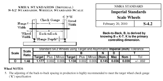
I thought Wheel Note 5 was very important, it states: “The adjusting of the back-to-back spacing is highly recommended to meet the target wheel check gauge (K) specification.” Here is the NMRA pointing out that there needs to be flexibility in the back-to-back dimension to meet the more important dimension of the inside of the flange to the back side of the opposite wheel dimension.
With this I’ve started a new page to record the different dimensions of different manufactures wheels. I was surprised how far off some of them where.
Turns out the new NMRA standard is where I wanted to move my standard to. I think the 0.145 wheel is a nice compromise in width and there are already commercial replacement wheelset for the width from North West Short Line. I had already started to go there with the purchase of some North West Short Line replacement wheels for the Weaver drives.
My next experiments with thinning the Intermountain wheels are starting from setting the back-to-back dimension first and than machining the front of the Intermountain wheel to get to the desired width. This will be a lot more work than taking the material off the back, but I think it will make a better operating wheelset in the long run.

